Tuesday, May 7, 2013

Roden Blitz Omni Bus Stabswagen Opel 3.6-47 kit 723

Roden Blitz Omni Bus Stabswagen Opel 3.6-47 kit 723

Having put the Blitz Aero together in a day, and having enjoyed it so much, I decided it was time to build another bus. I will refer to this one as a Staff Bus, as the kit title is rather a mouthful.

About the bus. According to the information with kit these were used in all theatres of operation. It was in effect a kind of mobile office or command centre. Pictures, plans and information about all the Opel Bus types can be found on Piet Van Hees very useful site http://www.pietvanhees.nl/blitzbus/

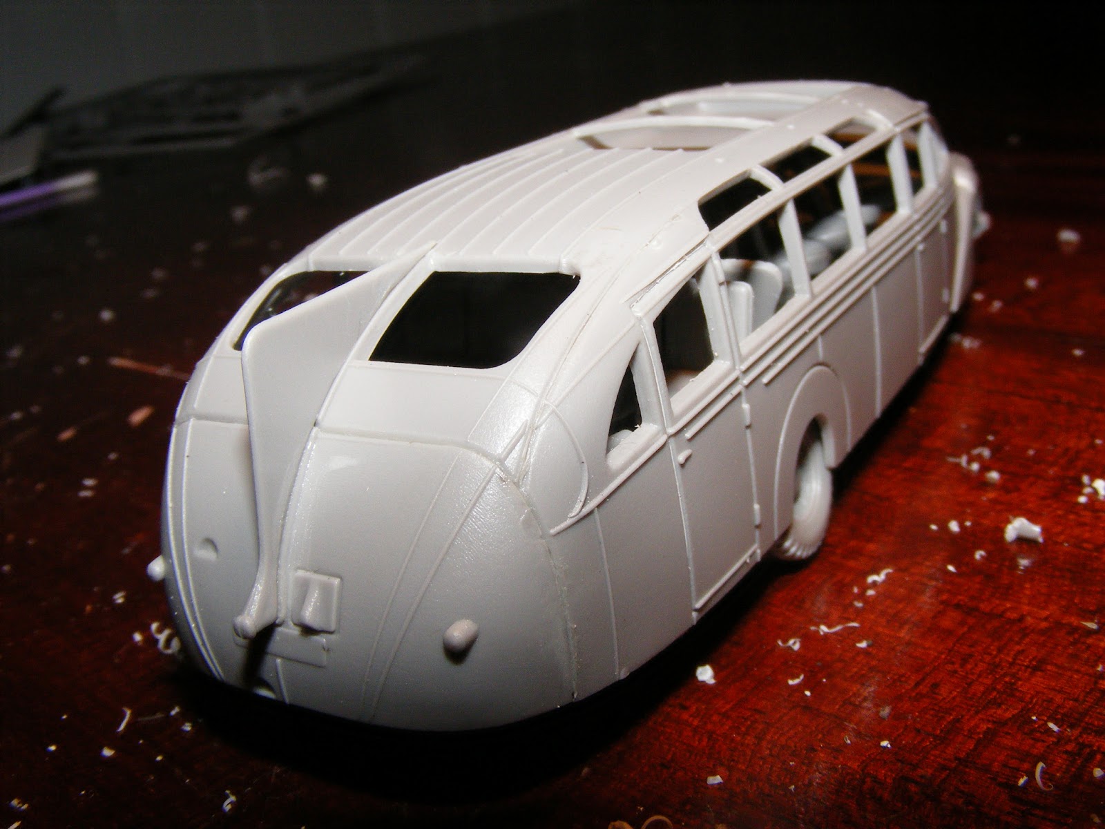
About the kit. This kit shares many sprues with the Roden Opel Blitz W39 bus. Chassis is identical. Body is identical. The main difference is the inside furnishings which consist of tables, shelves benches, a radio, enigma machine (or perhaps its a typewriter). This version also has additional wooden decking on the roof, and etched roof racks, much longer than that which the standard bus was fitted with.Etch covers for the side windows are also supplied.


About the build. As this kit has so much interesting internal detail, I decided to open both the front side doors, and the large rear door, cutting these out carefully with a fresh exacto blade. Despite this not much of the interior will be visible, but it will make the vehicle look much more interesting. I was going to thin down the cut out doors, but period photos show the doors were quite thick. Unlike a tank hatch which is solid metal and comparatively thin, the doors on these vehicles had an outer and inner covering, being essentially hollow in the middle, so were quite thick.

Below are test fits of the floor/chassis to the body, so far all are good fits.


Update Saturday 11 May. I have to admit this is a very enjoyable build. I decided it would be easy enough to build this one so that the body can be removed to show the interior detail, so decided to improve the interior a bit. I won't be going crazy on interior detail, just some improvements. I started with the floor.

 Period photos show that wooden slats of a pallet like construction were laid over the much of the floor of these buses. Wood was plentiful, and  timber slats would have been cheap to manufacture and to fit, and add very little to the weight of the bus. Non slip metal tread plate would add to the weight of the bus and be more expensive. Rubber mats would have been in short supply and would wear out quickly in rough conditions on operations. The timber slats would have been assembled in sections and would have been removable when needed for cleaning and maintenance. The wood slats would have dealt well with wet and muddy conditions, the water and mud being trapped in the gaps between the slats.

First job was to fill the holes where the seats would go (the floor in the kit is same as the standard Opel bus) I used 0.010" x 0.020" & 0.020" x 0.020" evergreen strip styrene (Item 100 & 120) glued to the floor. Not a hard job, but took an evening while watching/listening to TV to provide some distraction for the mind while working on what is otherwise a slightly boring task.


I also decided to not use the etched roof rack. It looks reasonably OK, though a bit too flat for my taste.
I built a roof rack out of 0.020" Evergreen Rod (Item 218). I drilled holes in the roof for the supports, and simply cut the lengths to fit and glued them. Not hard but requires accurate measuring and cutting and is quite time intensive, it took a few hours. To get curves I simply rolled the rod around items of varying diameters to get tighter or larger curves as required. Items such as pens, screwdriver shafts etc. The rod is quite thin which makes it quite flexible and very adaptable to being curved.


TO BE CONTINUED....................................

Monday, May 6, 2013

Roden Opel Blitzbus Ludewig Aero 1937 Kit 724

Roden Opel Blitzbus Ludewig Aero 1937 Kit 724

Hello. Having built the Roden Opel Blitz bus, and the Opel Strassenzeppelin bus (kits 720 and 725 which also have posts about them on on this blog), I decided to build the Aero variant.

About the bus. Like the Strassenzeppelin, the Aero was built on a standard Blitz chassis, in 1937. It has different body work, and a luxury interior. At least one photo shows one of these buses with WH numberplates and Notek light, photo said to have been taken in Russia. Given the constant requirement for  replacement motorised transport during the war, & the strains on the wartime industry to meet the needs of the war, its hardly surprising that existing luxury buses were also sequestered for military service

About the kit. This kit shares many sprues and parts with other Roden bus kits. The interior seating, wheels and front apron are same as supplied with the Strassenzeppelin. The motor &  chassis, as with the Strassenzeppelin are common to the standard blitz bus. In this kit both standard headlights and blackout headlights are supplied, though the instructions advise to use standard headlights. A Notek light is supplied also, being located on the common sprue with all the engine parts, though the instructions also show this as not being used. No decals are supplied. As far as I can see this kit has identical sprues to kit 728, Opel Blitzbus Aero (WWII service) the only difference being that kit 728 will have WH numberplate decals, and the instructions will show to use the blackout lights and Notek light, and different painting instructions.


About the build. Having built the chassis twice before on other Roden blitz buses, I decided to go straight for the new parts - roof/cabin, sides, rear end, radiator and 'shark fin to see how they fit. The fit was surprisingly good. Some filler will be needed where the side meets the mudguard, but this will be minimal and has good access to sand to an invisible join.The design of these pieces  was so much better, and easier to assemble compared to the multiple pieces that made up the nose on the Strassenzeppelin

 Next job was to see how well the underneath of the chassis fit into the completed bus body shell. I was pleased to find the fit is very good, it fits easily, neither too tight or too loose, in the test fit in the picture below. I found neither of the previous Opel buses I built fit as well as this one.

I found some more time and now the bus is complete, assembly wise, less than 24 hours after being started.  I have not glued the chassis and body as these must stay separate for painting and adding of windows.


 I have to state this was the easiest assembly of the Roden Opel Blitz buses. Its not simply that I am more used to the assembly as the body assembly on this one is unique - all new pieces, though the chassis is unchanged from the other Blitz Buses. As already mentioned the seating is the same as the Strassenzeppelin. Period photos show the seating really was the same as this, with the seats set at 45 degrees, the rationale being it allowed better viewing out the windows. These vehicles were also said to have a fridge for champagne bottles - though no fridge comes with the kit.

I have only temporarily attached the wheels for these pictures, they also won't get permanently attached until painting is finished. The front axle is very fragile (the same assembly as on the Roden Blitz Truck and Opel Maultier, so it will definitely be put aside until all other painting and assembly is finished.
The glue will be left to harden for a few days, then painting will commence.

TO BE CONTINUED.......................................

Saturday, May 4, 2013

Hobbyboss German Rail Transporter for Karl Gerat Kit 82906

Hobbyboss German Rail Transporter for Karl Gerat Kit 82906

Sunday 5 May 2013.

About this post. I commenced this build a couple of weeks ago and took a number of "in progress" pictures. Unfortunately the storage device the pictures were on became corrupted and I lost them all, so I only have pictures of the  major pieces assembled.

The kit. This contains 7 sprues of plastic parts, 1 set of decals, painting guide and instructions. These can be viewed on Henk of Holland's site. All parts are neatly and crisply cast, with very little flash.

The Build. The build was quite straightforward and easy, aided by excellent instructions. Two issues need to be mentioned.

The first is minor. Some of the wheel hubs that the axles fit into needed a small amount of enlargement. This was easy to scrape out with a knife, and the wheel sets fit better as a result. This was only one or two hubs on each bogie the rest were fine.

The second issue is not so minor. The outside of the bogies (parts B7 x 2 and B8 x 2) have large injector marks. Some were slightly raised some were slightly sunk in. All were hard to deal with as their is a lot of detail very close to the injector circles. Fortunately these repairs are largely covered by additional parts that are fit to the bogies. There were 11 injector marks per piece, so in all 44 to fix on the bogies. It didn't take too long to fix, but it would seem this was a crazy way to cast these pieces - if these injector marks were on the other side they would be completely unseen. The exact same problem was also on parts B5 x 2 and B11 x 2, which are the long side parts of the large overhead frames that hold up the Karl. Unlike the bogies, the areas the injector marks are on will not be covered by other detail, so a lot more care is needed in dealing with them. Again there were 11 injector marks per part, 44 in total If the injection had been set up to occur on the other sides of the parts they would be near invisible, except on very close inspection.


 The transporter was sprayed with Hobbyboss acrylic black, then a spray of H337 "Grayish-Blue", leaving the areas that would be in shade with a lighter coating, to create some modulation, depth and contrast between the different surfaces and angles. Still a lot of painting to do, better pictures will be taken and posted.

The model is  not properly assembled yet, some 'Blu tack" is holding the frame assemblies up. Final assembly will occur when painting is finished,


Update 16 July 2013. The components have had a light spray of Aqueous Hobby Color, Sand Gelb, and have had washes of black and brown, being watered down Life Color acrylics. Heavier washes on the springs with brown to simulate age & some oxidisation.


TO BE CONTINUED............


Sunday, April 28, 2013

Hobbyboss 82905. Morser KARL-Gerat 040/041 Late version

Hobbyboss 82905. Morser KARL-Gerat 040/041 Late version

Sunday 28 April 2013

About this post. I have been working on this kit for a few weeks, but had not got around to starting a post for it, though I took many 'in progress' pictures to put in the post once it was started. However the SD card that the photos were on became corrupted and I cannot view or retrieve any of the pictures ! That will be a lesson to me about delaying starting a new post, so this build/review lacks the usual 'in progress' pictures.

About the subject. I won't discuss the history of "Karl" as that information is easy to obtain. There are plenty of reference books on the Karl, as well as numerous pictures on the web. Wikipedia has a short history of the 7 Karl's built. I will mention differences where it relates to the kit.

About the kit. Several sprues in this kit (see Henk of Holland site which has scans of the instructions which include the sprues). A set of 'rubber band' style tracks, a set of springs for the gun recoil as well as a small metal rod.  This kit allows any of Karls numbered 3 - 6 to be built. Karls numbered  1 - 2 had a visibly different road wheels, as well as having 8 wheels per side, Karl 3 - 6  has 11 roadwheels per side. Anyone wishing to build Karl 1 - 2 needs to buy Hobbyboss kit 28904 "Initial". Decal sheet in this kit for Karl number 3,4,5 & 6.

About the build. Almost all  parts are well cast and clean - very little flash or cast lines to remove, though a little of this work was needed on some parts. Almost all parts are engineered to be a good fit without need for filler or sanding. One exception were the parts that hold the gun to its carriage - parts F25 and F26. I found I had to sand and enlarge the circumference of these a little to get a good fit. The tracks are a good, if somewhat tight fit. I carefully gently stretched the tracks to add a few millimeters to allow track sag to be gained. Period photos show quite a bit of track sag. The tracks were joined with liquid CA glue, and this was brushed on the upper road wheels and toothpicks were wedged in place around them to ensure the tracks held their sag while the glue dried.  The kit provides parts for the long barrelled and short barrelled versions (known as 040 and 041). References advise that the barrels were interchangable, though it was a heavy workshops job to change from one type of barrel to the other. The short barrel was 600mm wide, the long barrel was 540mm wide. The long barrel fired a lighter round, but at higher velocity. The mesh grille next to the drivers compartment is not very well cast, the mesh being too thick. I improved it but it would be better replaced with mesh. The metal springs are hidden inside the gun casement. Karls spent most of the war in their barracks in Germany, only being sent out for specific operations on a few occasions during the war. For this reason I have chosen to paint this one in a fairly neat and clean appearance.

Overall impression. A good kit, this opinion based on little clean up of parts needed, almost everything fit well, clear instructions how to assemble. Would have been nice to get one each of the rounds for the 040 and 041 barrels, to sit on the rear loading cradle. This kit does not need advanced skills to get a good result, and period photos show a variety of paint schemes can be chosen.


TO BE CONTINUED


Saturday, March 16, 2013

ACE kit 72262 ADGZ (Fu) Mittleren Panzerwagen M-35


ACE kit 72262 ADGZ (Fu) Mittleren Panzerwagen M-35

This is another kit I bought soon after it was released, with the intention to build it promptly, but some years have passed, with the box gathering no attention, only a light coat of dust. I decided a week ago it was time to get this bizarre looking vehicle built.

Brief History. 14 ADGZ were inherited from the Austrian army and another 25 were produced in 1942. The Encylopaedia of German Tanks labels this vehicle as a "Polizei-Panzerkampfwagen ADGZ".

These vehicles were very lightly armed and not suitable for front line use. From 1942 these vehicles were used to fight partisans in eastern europe, particularly in the Balkans.
Despite the relatively low production numbers of these vehicles, quite a lot of period photos exist. Photos indicate these were in use in dark grey and dark yellow paint schemes, as well as winter whitewash in snow season.

In  the box. 4 sprues of parts, one set of instructions, one small sheet of decals.


There was a fair amount of clean up of parts, as occurs with short run kits. Most parts had cast lines, and the suspension/axle areas needed the most work.

 Having read a review I expected the worst with the joining of the upper and lower hull, and with irregular axle level between the front and rear end wheels and the middle sets of wheels.  I found the wheel sets sat evenly when I test fit the wheels, perhaps over zealous clean up of axle areas can create uneven axle heights, in any event, happily I did not experience this problem. So onto joining the upper and lower hulls.

 I also decided to clean up the join along the top and bottom halves of the hull after joining them, rather than before, so as not to damage the angled joint, which would be hard to fill and sand back to the correct angle. Again I did not experience the problems I read in a  review, the join was fine, just a tiny irregularity on one side had to be cut off along the join line to get a good tight fit, provided pressure was applied. I applied liquid cement and kept  heavy pressure on the two halves for some time to get a good tight bond, having done that there was just a little flash to sand around the join and no filler needed. Most pleased with that easy win.

The four parts to the turret needed a small amount of filler on the rear join and a tiny amount on the top on one side. The front panel of the turret had a lot of scraping and sanding to get a neat fit.


Having built the major components with relative ease and speed, I then decided I could spare time and energy to cut out the engine louvres and replace these with plastic card slats in the open position, to improve the look of the car. Period pictures also show these louvres in the open position more frequently than in the closed position (maybe the car had ventilation or over heating issues). I also decided to cut the top half of one door out, in the open position, also frequently seen in period photos.

Then the start of a paint job, prior to fixing small details such as lights, as I find these get in the way when painting and small details are easily broken in the handling on the way to final assembly, so I usually add these last, and no change to that strategy with this build.

Vehicle was then given an undercoat of Tamiya Matt Black Enamel & and a top coat of Revell Matt 77 Grey


Updated Sunday 14 April 2013. A bit more progress achieved. Wheels on and light spray of dust, mainly on lower areas.


Update Sunday 28 April 2013
This one is now very close to complete. I have left some small parts off, which may be added later, these being the two shovels, number plates and turn indicators. At this stage I also have not added the 'bedframe' aerial. The aerial is quite well cast, so would take little time to attach it. Door handles added from bent pieces of copper wire, open door made from plastic card, cut to shape.


Update Sunday 05 May 2013. I decided to lighten the paint job. Period photos show these vehicles in what looks to be dark yellow, as well as dark grey, also winter white wash. I used Hobby Color acrylic H79 dark yellow, lightened with a little white.Still need to tweak the finish a bit but here is the progress so far.


Saturday, February 2, 2013

Diorama Build

Diorama Build

Hello. Last year I built a large diorama for the BP-44 train which turned out reasonably well, and provided me with a good space to display a (half) BP-44 train and various other models (picture below). I've not given that diorama an official title,  I usually refer to it as "Germany, Spring, 1945".


I still have other armoured train models, and decided to build another large diorama in order to display more train models as well as other vehicles. Trains are long so displays are also necessarily long. And there is a limit to how wide they can be to be practical to display or move about. The previous diorama was just under 1200 millimeters long and 200 millimeters wide (built on a store purchased shelf of those dimensions) . This new diorama is just under 1100 millimeters long and 260 millimeters wide, also to be placed on a store purchased shelf. The reason the dioramas are built a few millimeters short of the shelf edge is to allow a clear acrylic case to be placed over them, to protect the diorama from all manner of hazards, in particular dust.

The base of this diorama was built on 3 mm thick MDF (a compressed cardboard type of wood). This was a mistake as the length of the diorama meant it could flex when picked up (which would damage the future scenery). To remedy I bought another 12 mm thick piece of MDF, cut it to size and glued it under the 3mm thick piece. This has made it very stable, no flexing at all.


Like the 'Germany 1945' themed diorama, I decided to have a lower and upper area of the diorama, in order to give the scene some interest and depth.

 The setting for this one is unclear yet, but it will be mid to late war, and set in a near coastal area of the Adriatic Sea or Black Sea. In general terms this means the Balkans or the South Eastern area of the (former) USSR. This potentially means the diorama could be in the Crimea, Southern Ukraine, Romania, Bulgaria, Albania, Montenegro, Bosnia, Croatia, Slovenia or northern Italy

 When I have the basics of the diorama a bit further advanced I will make a clear decision as the location will influence what vehicles are placed on the diorama, final colouration of ground, type of trees, plants, structures etc.

The raised up sides and rear of the diorama are 3 mm MDF, glued together, and to the base. The rock face is corrugated cardboard, crumpled up, and attached with lots of white PVA glue. The white PVA glue softens the cardboard to help get some irregular shapes and angles, and the corrugations in the cardboard look a bit like layers of rock strata. When dry I then mixed up "plaster of paris" powder with sand from a nearby beach to give it some 'grain', and applied this roughly over the rocks and base with a large paintbrush, to help give it some texture and irregular shape, as occurs in nature.

When dry I then watered down some cheap artists acrylic paint, and roughly applied all over the surface to completely cover, and remove all trace of the white colouration. I also dipped the edge of the brush in a darker brown to give some depth and variation of shade in some parts. Still a long way to go with paintjob, and base. 


 At this stage I am working on the lower area of the diorama, and will work upwards to the top, where the railway lines will be.

Update Sunday 3rd February 2013. Today I used watery acrylic paint, mixed with a sand from a beach to paint the low lying area between the two high features. The idea is that this area is a low lying wetland type of area (not a swamp), that drains out to the sea. No sea water will be sculpted as insufficient space, and I want most of the low area to be usable for placement of objects, vehicles, figures. The setting is the 'dry season' with very little water draining under the bridge (presumably Summer for most places) but in Spring or the 'wet season' a greater depth and flow of water would be draining out to the (nearby) sea.

As can be seen in earlier pictures posted, the intention is to place a bridge between the gap, for rail lines to run across. The earlier pictures showed a wooden trestle type of bridge, I'm now leaning towards a stone bridge. Part of the reason for a stone bridge is it will leave some clear space underneath, which will look  better and be more useful than the trestle bridge which takes up all the space. I will investigate what I can use in this space.


Update 16 March 2013. Its been over a month since the last update on this diorama. I had decided that the rock faces were too bland and plain. I decided to modify them with some rocks protruding, but this didn't work. I then stripped all the rock walls away and started afresh. I found the best thing to represent rock is actual rock. Luckily I build my dioramas sturdy as this added a few kilos to the weight. Not finished yet but I like how its going. No pictures of the failed second version, the pictures below are rock face Mark III. Vehicles placed randomly for a couple of pictures. Still much to do.


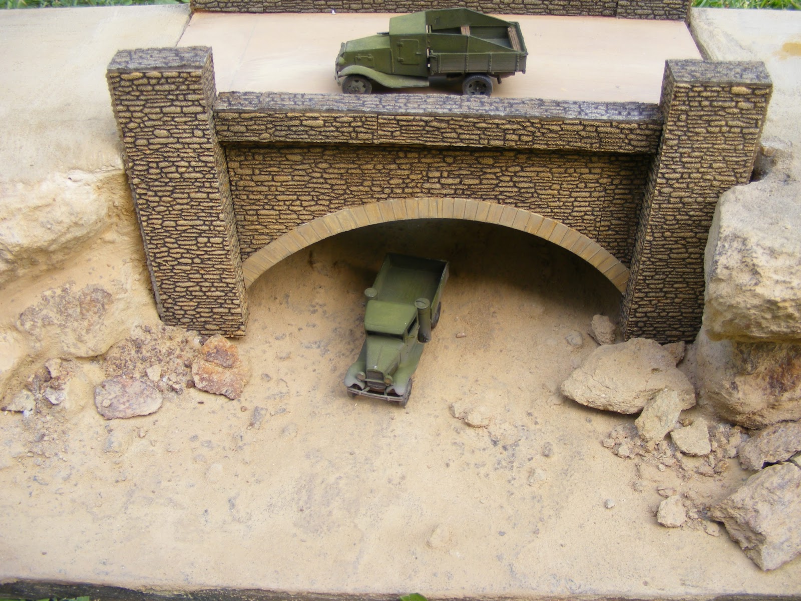
Update 17 March 2013. Today have worked on the bridge which was scratch built, cut to size to fit the diorama from scrap wood. Wood was covered with 'Busch' brand stone wall sheeting (HO 7404), cut to size. Still a lot to do to the bridge, including improving its colours


Update Sunday 14 April 2013. 4 weeks since the last update, I have been progressing the diorama, but have not had time to update this blog. I'll attempt to remedy that now.

After all the 'stonework' was applied, the bridge was painted by brush with water based acrylics. The colours were mixed to approximately match the surrounding rock face. The concept being that the bridge stonework was constructed with rock quarried on site.

In the below picture the stonework on the bridge looks a bit darker than the surrounding landscape, the paintwork on both the landscape and bridge is not yet complete. Trucks are on the bridge for the photo to illustrate the scale size of the bridge. 


Next job was to lay the base for the railway tracks. I measured and cut lengths of reinforced cardboard as the road base for the track. I used some rail wagons to ensure correct width between the two tracks and bridge sides.


Next job was to lay the track. These models are 1/72 scale. A few manufacturers sell rail track in 1/72 scale, these being Hobbyboss, Italeri and UMMT. Other manufacturers supply a length of track with their rail vehicles, such as UM and ACE.  Most of these choices vary in detail and appearance, and are not compatible with each other, due to differing profile of the rail track, sleeper width length and height and spacing, and slight variances in gauge (they represent Standard Gauge and Russian Broad Gauge in 1/72 scale. I was not perfectly happy with any of these choices. For me the best choice is model railway track such as Peco. Its also not perfect but is better than any of the others.

The only problem with Peco is that is 1/87 scale, so is too narrow for a 1/72 scale diorama. This diorama is 1/72 scale, with is what most of western europe used in the 20th century and still does. This diorama may be set in eastern europe.  The germans energetically set upon converting russian broad gauge to european standard gauge as quickly as they could as soviet territory fell into german hands from June 1941. By the end of 1942 most of the soviet territories under german control were european standard gauge. This was not for convenience this was an urgent neccessity.  Railways were the fastest and most efficient means of moving vast quantities of supplies, men and war machinery  in the mid 20th century. What was more important was that trains ran on coal and water, neither of which was in short supply, and could move millions of tonnes of supplies each year without using petrol, which was in increasingly short supply during the war, and always urgently needed by the mechanised and motorised armies.

Converting the rail from russian broad gauge to standard gauge was not a complicated engineering job & only required simple tools. One rail was loosened from the sleepers (or ties), then levered inwards a few inches and refastened.  The germans used work gangs of local labour in occupied territories to do this work. Vast numbers of civilians remained behind in the occupied territories, and had little choice but to work for the occupying forces. Period photos show men, sometimes in bare feet, and women, doing heavy labouring work under supervision on railway tracks in eastern europe.

Standard gauge is 1435 millimeters, measured  from inside rail to inside rail. In 1/72 scale this equals 19.93 millimeters, close enough to round to 20 millimeters. HO scale track (1/87 scale) is 16 millimeters. This is too big a difference to not address, so I used a razor saw to cut down the middle each length of track, took a few minutes to do all the track. I then glued each rail on marked out lines, so that they were 20 millimetres apart. This leaves a gap in the middle, but contemporary photos show that the track almost always has ballast and soil over the sleepers between the rails so the 'gap' will be easy to remedy.


For information, russian broad gauge in 1/72 scale is 21.11 millimeters, so separating the tracks by an additional 1 millimeter from the above would create close to correct scale for russian gauge.

To make the "ballast" for the track I used some 'N' scale ballast, mixed with beach sand (picked up from a nearby beach) and watered down white woodworking glue (Shelleys or Elmers) a big squeeze of artists of brown acrylic tube paint. Unlike in the modern era, period photos of rail tracks in Russian territories in WW2 usually show mimimal use of crushed rock ballast, mostly soil and sand seems to have been used, so I have tried to replicate that here.


I have used artists acrylics, mixed in varying shades around the tracks and ballast, and used Mr Hobby acrylics to lightly spray the rock wall features to give a bit of depth and highlight the formation of the rock.

TO BE CONTINUED..........................